Data optimisation for cellular IoT: Part 2

Martin Varga of Anritsu Europe
In the part one of the blog Martin Varga of Anritsu Europe said that The Internet of Things is not just about new application and services: it embraces the whole technological spectrum that enables all of these innovations.
Control plane EPS optimisation
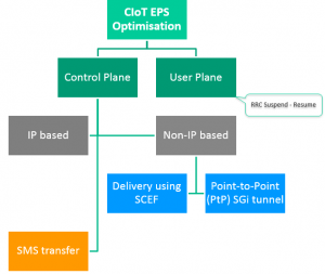
Control plane EPS optimisation transfers the data in non-access stratum PDUs, which means that the user data are attached to signalling messages transferred between the user equipment and the MME mode without triggering data radio bearer establishment. Both IP and non-IP transfers are supported. IP data are transferred through the SGW and PGW gateways whereas non-IP data are transferred via SCEF (Service Capability Exposure Function), which gives an abstraction into underlying IoT services or via a Point-to-Point SGi tunnel between the PDN gateway and the IoT application server. In case of IP data transfer, further efficiency is achieved by IP header compression (ROHC).
Fig.4 shows an example of mobile originated data transfer with control-plane optimisation. User data are contained in a non-access stratum PDU attached to the RRC message.

Figure 4: MO data transfer in non-access stratum PDU [source: 3GPP TS 23.401]
The support of control plane and user plane optimisations are indicated in signalling messages on both the UE and network sides. Both the UE and the network may support both control and user plane optimisations.
For Cellular IoT EPS optimisations, the UE may indicate support for control plane EPS optimisation, user plane EPS optimisation, Attach without PDN connection, S1-U data transfer and header compression.

Figure 5: Summary of CIoT EPS Optimisation
Although these techniques for data transfer optimisation were developed for cellular IoT devices, they can equally be used by devices not related to IoT applications.
Testing solution
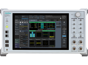
The development of these optimisation techniques has led to a need to test and measure the data transfer between IoT devices and IoT application servers, whether it is during the development cycle of the IoT device or in a phase of testing a direct IoT application. The requirement is for a test instrument capable of simulating the cellular IoT network which can offer a radio access network with direct connection to the application infrastructure. The Anritsu MT8821C Radio Communication Analyser provides simulation and measurement capacity to effectively test and measure Cat-M1 and NB-IoT devices. It will also test the RF performance capabilities of the devices, while offering the benefits of direct IP connectivity from the device under test to the application server.

Figure 6: Anritsu Radio Communication Analyser MT8821C
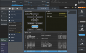
In Fig. 7. Anritsu’s Radio Communication Analyser MT8821C shows the signalling trace where the user can see signalling messages throughout the communication. The signalling trace is helpful to identify errors during registration or simply follow the signalling procedures during the test. Additionally, the sequence monitor is showing the current status of communication between a simulated network with the MT8821C and a device under test. The UE Report provides important information about IMSI, IMEI and PDN type of connected device.

Figure 7: Signalling messages view in Anritsu Radio Communication Analyser MT8821C
The IP Data tab (Fig. 8) in Anritsu Radio Communication Analyser MT8821C gives direct access to ping and iPerf functionality. The user can easily check IP end-to-end data connectivity between the application server of the MT8821C and the device under test or trigger downlink/uplink streaming for IP data throughput testing.

Figure 8: Ping function for end-to-end data connectivity check
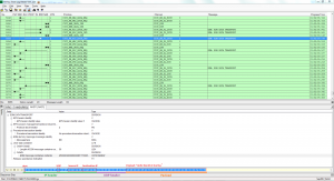
After the simulation, the user can see a detailed signalling log in the external application Anritsu Trace Log Viewer. The example below (Fig. 9) is showing UL IP packet encapsulated in ESM: ESM DATA TRANSPORT signalling message. Details of the IP packet such as IP version, protocol, source and destination address, payload of packet and other elements can be decoded from a HEX string present in the log.

Figure 9: Trace Log Viewer showing UL message encapsulated into signalling message
The author of this blog is Martin Varga of Anritsu Europe
Comment on this article below or via Twitter @IoTGN
